
Technical Description
Efficiency is paramount
As described previously, Max-i is probably the most efficient fieldbus in the world. This is very important because efficiency is a much better way to increase the data rate than speed because it does not reduce the signal-to-noise ratio (S/N) and therefore does not increase the error rate! If for example the probability of a bit failure (p) is 10-7, which is usually accepted in a field bus system, just a factor 2 (N) increase in speed, which reduces the S/N to the half, will reduce this to approximately p(1/N) = 3.2 x 10⁻⁴, which is unacceptable.
The S/N is the ratio between signal power and noise power, but for digital communication, S/N = (Eb/N0) x (Fb/B) where Eb is the energy (power x symbol-time) in each bit and N0 is the noise power per Hz or noise energy accumulated over the time of the bit. Eb/N0 is called the normalized signal to noise ratio or signal to noise per bit, and the total denominater N0 x B is the total noise power, which is let through by the bandwidth. Fb is the number of bits per second (channel data rate) and B is the necessary bandwidth to transfer these bits. Fb/B is therefore a measure of the efficiency of the communication and is the reciprocal of the so called "gross" link spectral efficiency. The more bits, which can be transferred for a given bandwidth, the better, but only if it does not reduce the signal level of each symbols. If for example PAM4 (Pulse Amplitude modulation with 4 levels per bit) is used, two bits are transferred per symbol as shown below so the necessary bandwidth B is only the half, which alone doubles the S/N, but because the minimum voltage swing is simultaneously reduced to 1/3 and the signal power is proportional to this squared, the S/N may be redused a factor 9/2 = 4.5, which has a tremendous impact on the error probability.
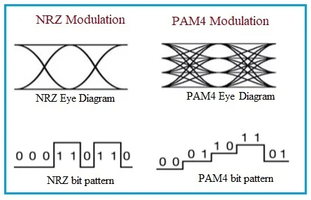
Besides, it gets much more difficult to detect the signal, which increases the error probability even further, because 3 detection levels are necessary and only the one in the middle is not affected by the signal amplitude.
In case of capacitive loads and/or changes in line impedance, which are almost unavoidable in practice - especially on long lines, both NRZ, which is used by most RS-485 systems like Profibus and MODBUS, and PAM4, which is used for example for high speed Ethernet, will suffer from bias distortion. A row of zeroes or ones may charge the line towards the negative or positive voltage, which makes the signal asymetrical so that the length of a 0-bit and a 1-bit are no longer the same in case of a limited slew rate. With Max-i, the length of the pulse, which charges the line towards the positive supply rail, is always the same as the pulse, which charges the line towards the negative supply, so there is never any bias distortion, and due to the 3-level hysteresis as shown in next chapter below, the triggering level is always in the ideal point in the middle.
For NRZ with square pulses where at least a part of the 3rd harmonics is wanted, Fb/B may be set to approximately 0.7, and for Manchester coding, which is self-clocking, it is approximately the half = 0.35. For Max-i, which is also self-clocking, it is approximately 0.5 because a row of 0-bits may be regarded as a synthetic sine-wave with no 2nd, 3rd and 4th order harmonics. If N0 is considered constant, the relationship between the S/N of a NRZ coded signal and Max-i is therefore approximately (Eb-Max-i x 0.5) / (Eb-NRZ x 0.7), but in practice it is even bigger because the coupling impedance of the noise is capacitive and therefore inversely proportional to the noise frequency and therefore increased more than proportional to the bandwidth.
For a given data rate, the S/N is also inversely proportional to the mumber of bits necessary to transmit the payload data since it increases the necessary communication speed, which reduces the energy Eb in each bit. Therefore, Max-i is designed for an absolutely minimum amount of bits:
- It is a multimaster bus with event-oriented communication so that it is not nessasary to poll all sensors all the time at a very high speed to insure a short responce time. This also makes it possible to have any number of control panels in a process plant and add any number of debuggers.
- It uses the very efficient publisher/subscriber model where published values may be utilized simultaneously by any number of devices. This makes it for example possible to update all traffic lights in the same direction simultaneously as with traditional point-to-point connections between the controller and each lamp - even at a very low communication speed. It is also very practical for information displays in for example airports and train stations.
- It is possible to transmit individual data to more devices in the same message like DMX512. This is extremely useful for example for stage light and lighting in large rooms and halls where it avoids visible delays between lamps like the "Mexican Wave" known from DALI. It is also extremely useful for robots, cobots and CNC-machines where it ensures that all axes are updated exactly simultaneously so that the machinery does not move in a zig-zag manner. If this option is used, each device receives its own 1-4 bytes plus 4 bits that are common to all devices and can be used, for example, to set a smoothing filter or to select between up to 16 different message types such as light and lamp movements like tilt, pan, zoom and gobo control.
- It uses synchronous communcation so that it is not necessary with a start and stop bit for every byte and no data-length information is needed to be able to tell when the telegram is finished, which typical saves 2 bytes.
- It uses a unique error detection method invented by Innovatic and developed in collaboration with the technical university of Denmark - DTU. Usually, the check bits are just generated over the message by means of a CRC-polynomial and added to the end, but not used for any other purpose. In Max-i, the entire telegram is instead scrambled with the CRC-polynomial so that the last 20 bits of the telegram just need to be known information, which can be verified, but can simultaneously be used for useful information, which would otherwise require up to 3 extra bytes as shown in the table below:
Message type | 8-bit | 4-bit data type | 1 bit | 7-bit Hamming code of identifier |
Boolean (TIME) | 0000,0000B | 1100B | 1 | xxx,xxxxB |
Boolean safety message | Serial number | |||
| Fixed-point value | Exponent | 0000B | 1 = unsigned 0 = signed | |
| Fixed-point BCD | Radix point | 0001B | ||
| Floating-point BCD | 0000,0000B | 0010B | ||
| RAW | 1110B | |||
IEEE 754 floating-point | 0011B | 1 | ||
| Text | Code page | 1011B | 0 = ASCII 1 = UNICODE | |
| Pattern | Pattern type | 1101B | 1 | |
| Lamp control pattern | 0000,0001B |
The scrambling increases the efficiency for unused data fields. If there are more than 20 consecutive 0 or 1 bits in the message, pure, short 0-bits are transmitted, which increases the efficiency factor Fb/B from 0.5 to 1. It also ensures a fairly predictable maximum telegram time even though 1-bits are coded in such a way that they are 3 times longer than 0-bits, which is the way Max-i handles bus arbitration between multiple masters.
Fieldbus systems like for example Ethernet and Profibus DP may look fast at first glance with their respective data rates of 100 Mbit/s and up to 12 Mbit/s, but for many practical applications, the S/N may be over hundred times lower for the same or even lower throughput due to low efficiency and often an enormous overhead - especially if IPv6 is used with its 128 address bits, which alone is approximately twice as long as an average industrial Max-i telegram with the long identifier!
On for example a 100 m trunk line, it takes Profibus DP 1.14 ms to exchange 5 output data bytes and 5 input data bytes with 32 devices at 12 Mbit/s (32 x (317 + (10 x 11)) / 12,000 ms = 1.14 ms) according to the Design Guidelines. The average response time to an event is therefore approximately 570 µs, and because Profibus uses a transmission line with a characteristic impedance of approximately 150 Ω and RS-485 communication with a dedicated Profibus transceiver like LT2876/LT2877, which has a differential pulse amplitude of 5.4 V under these circumstances, the energy Eb in each pulse on the line is ((5.4 V)2 / 150 Ω) x 83.3 nS = 16.2 nJ.
As a comparison, it only takes Max-i 180 µs to transmit 5 bytes event driven (or polled) on a 90 m, 50 Ω, balanced 4-wire line at a signal level of 13 V and a pulse width of 1 µs so Eb = ((13 V)2 / 50 Ω) x 1000 nS = 3400 nJ. Under these circumstances, Max-i therefore has a 570 / 180 = 3 times shorter response time than Profibus DP at at least a (3400 x 0.5) / (16.2 x 0.7) = 200 times better S/N!
Probably due to the low S/N at 12 Mbit/s, the Design Guidelines of Profibus DP recommend that if absolut minimum response time is not needed, the speed should be maximum 1.5 Mbit/s, which may be used up to a line length of 200 m. This makes Profibus DP further 4 times slower than Max-i for the same line length - a total of 12 times and still with at least 25 times lower S/N. If there are less devices than maximum on a segment, the response time of Profibus DP will of course be shorter as the formula shows, and if more segments are connected together as a line and/or there is also slave to slave or asynchronous communication, it will usually be longer. Due to the event driven nature of Max-i, the responce time is almost unaffected by the number of devices for most practical process control systems!
Speed is really nothing to strive for for several reasons:
- It reduces the energy in each pulse and with that the S/N, which has an enormous influence on the error probability as shown above.
- It reduces the possible transmitter voltage if the slew rate (V/µs) should be resonable. An N-time reduction in speed may allow an N-time higher voltage for the same slew rate, which gives a N2-times better S/N and makes it much easier to burn through contact corrosion in connectors.
- It may create problems with spur cables. As a roule of thumb, the length of spur cables should be less than the rise time of the pulses divided by 6 times the propagation delay per meter of the spur cable. If for example the rise time is approximately 120 ns, as it is the case for Max-i, and PE cables with a propagation delay of 5 ns/m are used, spur cables up to 120 ns / (6 x 5 ns/m) = 4 m is allowed, but in practice even longer spur cables may be used, and Max-i may even use reflected wave switching at a reduced speed to allow free topology. Profibus DP does not allow spur cables at all, which may be very impractical.
- It increases the necessary receiver bandwidth and therefore let more noise through, and since the coupling impedance of noise is capacitive, high frequency noise from for example variable speed drives are much more serious than low frequency noise. As a result, it may be necessary with a lot of restrictions about cable spacing and how the cable must be drawn and connected, as it is the case for Profibus DP.
Max-i is very similar to CAN, which is probably the only other event driven multi-master bus based on bit-wise bus arbitration except for the old, obsolete STL-Net, but as can be seen from the table below, Max-i is not just much cheaper, but also much more powerful, reliable and safe.
Comparison between CAN and Max-i | CAN | Max-i |
Economy | ||
Possibility for single chip interface | Need CPU and PS | Yes |
Product certification and registration needed | Most protocols | Not necessary |
Use of unshielded, standard installation cables | No | Yes |
Maximum practical power transfer per segment | 384 W at 24 V 1) | ≥1 kW at 20 V 1) |
Maximum practical number of devices per bus | 64-127 | ≈1000 |
Environment | ||
Power saving mode / sleep mode (≤0.5 mA) | Only partial network | Not necessary |
Group control | No | 255 groups |
Data | ||
Multiple master bus with bit wise bus arbitration | Yes | Yes |
Publisher/subscriber model | Partly 2) | Yes |
Identifier length | 11 or 29 bit | 12 or 31 bit |
Multiple use of same identifier | No 3) | Yes 3) |
Number of addressing modes per identifier | 1 | 4 |
Local and global data and global poll of local data | No | Yes |
Possibility for temporary change of values | No | Yes 4) |
Maximum number of bytes | 8 | >1028 or infinite |
Different data to more devices in same telegram | No | Yes 5) |
Specified layers of OSI 7-layer model | 1, 2 | 1, 2, 3, 4, 6, 7 |
Setup attributes per I/O (OSI layer 6) | 0 | 16-1024 |
Reliability | ||
Unshielded cable | No | Yes |
No termination resistors = high failure tolerance | No | Yes 6) |
No bias distortion at capacitive loads | No 7) | Yes 7) |
| Ideal triggering level not affected by attenuation | No 8) | Yes 8) |
Line-ringing between devices during arbitration | High, but damped | Low (short pulses) |
Sensitivity to voltage drops in negative supply | High 9) | Low 9) |
Uncritical timing on all bus length and no setup | No | Yes |
Timing not affected by galvanic separation | No | Yes |
Tolerant to contact or conductor failure | No | Up to 2 contacts 10) |
Contact fritting | No 11) | 0.15 - 0.2 µm 11) |
Typical transmitter power / total power loss | 0.2 W / 0.4 W | 3.4 W / 1.3 W 12) |
Receiver hysteresis | 0.1-0.2 V | ±1 V, 3-level |
Sensitivity to vibrations and low temperatures | Crystal oscillator | RC oscillator |
Safety | ||
Error detection | 15-bit BCH 13) | 20-bit CRC |
Protection against masquerading | No | 7-bit Hamming code |
Detection of wrong number of telegrams | No | 8-bit serial number |
Predictable response time | No | Yes, deterministic |
Designed for IEC 61508 SIL 3 | No | Yes |
Speed | ||
4-bit/20-bit polled values/s on 1 km line | 612 / 530 | |
4-bit/20-bit polled values/s on 1.5 km line (1.5 times slower) | 480 / 350 14) | |
4-bit/20-bit event driven values/s on 1 km line | 1136 / 880 15) | |
4-bit/20-bit event driven values/s on 1.5 km line | 480 / 350 14) | |
4-bit/20-bit polled values/s at maximum speed | 9800 / 8472 | 30500 / 17600 14) |
4-bit/20-bit event driven values/s at max. speed | 18176 / 14080 15) | 30500 / 17600 14) |
1) 1500 W requires 5 x 4 mm2 flat cables with power supply from both ends. For the 384 W power level, CAN requires a very expensive thick DeviceNet cable (12.2 mm with 15 AWG / 1.65 mm2 conductors for DC).
2) CAN uses the publisher/subscriber model, but many protocols such as DeviceNet and CANopen need to establish a communication channel between devices before communication can take place and may even divide the network into masters and slaves.
3) Without this feature, it is not possible to make for example multi-way landing switches for LED lighting, and it is not possible to have more control buttons for the same process function or the same function in for example coupled trains, but most (all) CAN protocols such as DeviceNet and CANopen actually has a feature to prevent multiple use of the same identifier!
4) Most process values use 4, 20 or 36 bits, and it is possible to change a value temporary, which can save a lot of time during commissioning for example in case of sensor errors, to try an alarm limit or to simulate the presence of material.
5) Max-i can send individual 8-bit, 16-bit, 24-bit or 32-bit values to more devices in a common telegram with up to 1028 bytes and in this way ensure 100 % data synchronization and a very high efficiency for example for motion control, positioning systems and for stage light where Max-i with advantage can replace DMX512. Standard CAN (not CAN FD) is only able to transmit 8 bytes in each telegram.
6) In Max-i, the traditional termination resistors have been replaced by voltage clamps in each device. This gives a very high failure tolerance as the bus may be cut in any number of parts and each part can still work if it is powered up! This makes it very easy to make an error tolerant loop. The loop just needs to be power supplied from both ends as shown in the page: "Green Smart House Solution" and a error detection unit with two channels must then be connected to the two ends of the communication line. During normal operation, the two channels will receive the same massages and the error detector needs not to do anything, but if a message is only received on one channel, an error should be reported and the message should be repeated on the other channel so that the communication between all devices is preserved. A simple poll for group 255 (all devices) is then enough to find the approximate error location. The voltage clamps also reduce the ringing between devices during bus arbitration, reduce the power loss in the line termination to approximately the half compared to termination resistors and they utilize the reflections to improve the signal waveform and prevent bias-distortion due to noise rectification.
7) Bias distortion occurs in case of capacitive loads or lines if the output impedance of the circuit, which drives the line high, is not the same as the circuit, which drives the line low, as it is the case with CAN, where the line is driven high by a driver with a low impedance, but driven low by two 120 ohm termination resistors in parallel. This may cause a kind of signal rectification where it takes much longer time for a signal to go low than to go high, which destroys the signal integrity and makes it very difficult to chose the right triggering level. In Max-i, the driver is fully symetrical so even very high capacitive loads does not affect the communication.
8) Many fieldbus systems, which use termination resistors including CAN, have the problem that the low level is always 0 V, but the high level depends on the signal level and any attenuation. This makes it even more difficult to select the right triggering level. If the level is chosen too high, a high level may not be recognized in case of attenuation, and if the level is too low, the bus will be very sensitive to noise and it may take too long time for the signal to go low in case of bias distortion. In Max-i, the high signal level is always equal to the low signal level just with opposite sign, so the ideal triggering level is always in the middle no matter how much the signal is attenuated. This makes the signal/noise level even better in practice compared to other fieldbus systems. Below the very critical detection of a recessive CAN bit during bus arbitration is compared to the completely uncritical detection of a Max-i bit:
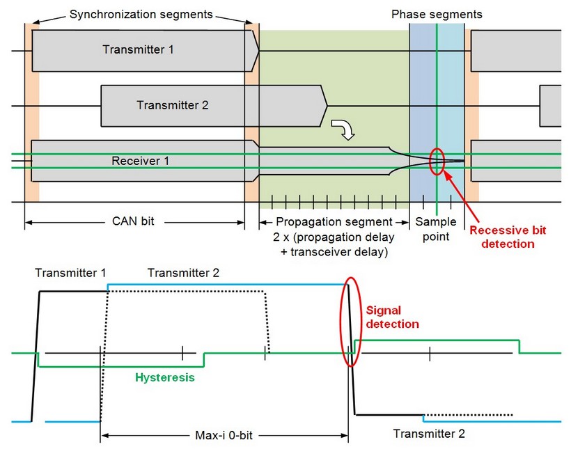
Note that in case of CAN FD, the bits in the high speed part after the bus arbitration are not NRZ coded, but coded with pulse width modulation (PWM) where each bit is divided in 4 parts where one part has one polarity and the three others the opposite. This makes it possible to distinguish between bits in the bus arbitration and acknowledge parts, which use NRZ, and bits in the fast part, which uses PWM, but it also makes it necessary with a 4 times bigger bandwidth for the fast part, which usually already uses a higher speed. This reduces the S/N enormous. If for example a 4 times faster speed is used in the fast part, the S/N is reduced a factor 16, so even though there is no bus arbitration in this part, the signal may be very difficult to decode in a reliable way!
9) The CAN transceiver is usually connected to the negative supply line so even though for example DeviceNet has two power supply lines in the cable for 0 and +24 V, they should not be used for driving heavy loads like actuators and lamps as any voltage drop in the negative supply line will cause bias distortion. Max-i uses the midpoint between the power supply lines as 0-V reference, but must then require that the voltage drop in the two lines are approximately the same, which in practice means that they must have the same cross section.
10) In case of a balanced 4-wire line, where the two communication conductors are connected together in all devices, Max-i will usually survive a failure on one of these conductors or connectors. If more power supplies are used, Max-i may also survive a failure on one of the supply lines so that Max-i is able to survive a failure on two neighbor conductors or connectors.
11) Usually, a fritting voltage of approximately 100 V/µm is required to burn through contact corrosion. Since the supply and communication voltage of Max-i is approximately 20 V, approximately 0.2 µm can be accepted. Below 3-5 V, no fritting can be expected. This makes CAN inexpedient for connections between for example tractors and trailers (trucks) and between train wagons.
12) When a transmitter is activated, two waves are generated with a typical power of 3.4 W in each direction. Because Max-i does not use any termination resistors, the current in each wave falls to zero after the time it takes for the wave to travel to the end of the line and back again to the transmitter. If for example a device is placed in the middle of the line, the two waves will arrive simultaneously, so the power will fall from a total of 6.8 W to zero after a time corresponding to the propagation delay of the line. If the device is placed at the end of the line, one wave arrives immediately, so the power falls from 3.4 W to zero after a time corresponding to two times the propagation delay. No matter where a device is located on the line, the energy (power multiplied by time) is the same, and if the line is shorter than the maximum length, the energy is reduced correspondingly. This reduces the emitted noise and enables battery operation and operation in explosive atmosphere. The power loss in the transmitter and the clamps depend on the supply voltage and the sum is maximum at maximum voltage.
13) In CAN, two bit errors may on rare occasion remain undetected when the first generates a bit stuffing condition and the second then removes a stuff condition (or vice versa), shifting the position of the frame bits between the two bit errors. The shifted area may lead to a burst error that is too long for the CRC mechanism.
14) In Max-i, it does not take longer time to poll a value than to transmit it event driven as the first and last part of the telegram are just transmitted by two or more devices.
15) Because CAN does not have any "babbling idiot" protection, it is not possible to reach this number of telegrams in practice without a completely unpredictable delay of low priority telegrams. Max-i may run even at 100 % and is faster than CAN for safety telegrams where CAN needs an extra layer and it is much faster if the possibility for different data to more devices in the same telegram is utilized as it is the case for stage light and motion control systems.
If you like CAN, you will love Max-i.
Specification
The Max-i specification can be downloaded here: www.max-i.org/specification.pdf
This page is created with WebSite X5 and updated February 9th 2026